Read/Write Head Technologies
The following information tells the development of rw heads technologies and it can be useful for you to learn about the hard drive data recovery basic knowledge.
Ferrite Heads
The oldest head design is also the simplest conceptually. A ferrite head is a U-shaped iron core wrapped with electrical windings to create the read/write head–almost a classical electromagnet, but very small. (The name “ferrite” comes from the iron of the core.) The result of this design is much like a child’s U-shaped magnet, with each end representing one of the poles, north and south. When writing, the current in the coil creates a polarized magnetic field in the gap between the poles of the core, which magnetizes the surface of the platter where the head is located. When the direction of the current is reversed, the opposite polarity magnetic field is created. For reading, the process is reversed: the head is passed over the magnetic fields and a current of one direction or another is induced in the windings, depending on the polarity of the magnetic field.
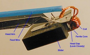 Extreme closeup view of a ferrite read/write head from a mid-1980s Seagate ST-251, one of the most popular drives of its era. The big black object is not actually the head, but the slider. The head is at the end of the slider, wrapped with the coil that magnetizes it for writing, or is magnetized during a read. If you look closely you can actually see the gap in the core, though it is very small. The blue feed wire runs back to the circuits that control the head.
Ferrite heads suffer from being large and cumbersome, which means they must ride at a relatively great distance from the platter and must have reasonably large and strong magnetic fields. Their design prevents their use with modern, very-high-density hard disk media, and they are now obsolete and no longer used. They are typically encountered in PC hard disks under 50 MB in size.
Metal-In-Gap (MIG) Heads
An evolutionary improvement to the standard ferrite head design was the invention of Metal-In-Gap heads. These heads are essentially of the same design as ferrite core heads, but add a special metallic alloy in the head. This change greatly increases its magnetization capabilities, allowing MIG heads to be used with higher density media, increasing capacity. While an improvement over ferrite designs, MIG heads themselves have been supplanted by thin film heads and magnetoresistive technologies. They are usually found in PC hard disks of about 50 MB to 100 MB.
Note: The word “gap” in the name of this technology refers to the gap between the poles of the magnet used in the core of the read/write head, not the gap between the head and the platter.
Thin Film (TF) Heads
Thin Film (TF) heads–also called thin film inductive (TFI)–are a totally different design from ferrite or MIG heads. They are so named because of how they are manufactured. TF heads are made using a photolithographic process similar to how processors are made. This is the same technique used to make modern thin film platter media, which bears the same name.
Developed during the 1960s but not deployed until 1979, the iron core of earlier heads, large, bulky and imprecise, is done away entirely. A substrate wafer is coated with a very thin layer of alloy material in specific patterns. This produces a very small, precise head whose characteristics can be carefully controlled, and allows the bulky ferrite head design to be completely eliminated. Thin film heads are capable of being used on much higher-density drives and with much smaller floating heights than the older technologies. They were used in many PC hard disk drives in the late 1980s to mid 1990s, usually in the 100 to 1000 MB capacity range.
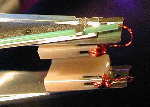 A pair of mated thin film head assemblies, greatly magnified. The heads are gray slivers with coils wrapped around them, embedded at the end of each slider (large beige objects). One feed line (with green insulation) is visible.
As hard disk areal densities increased, however, thin film heads soon reached their design limits. They were eventually replaced by magnetoresistive (MR) heads.
(Anisotropic) Magnetoresistive (MR/AMR) Heads
The newest type of technology commonly used in read/write heads is much more of a radical change to the way the read/write head works internally than the earlier advances, which were much more evolutionary and more related to how the head was made than how it worked. While conventional ferrite or thin film heads work on the basis of inducing a current in the wire of the read head in the presence of a magnetic field, magnetoresistive (MR) heads use a different principle entirely to read the disk.
Note: The correct technical name for first-generation MR heads is anisotropic magnetoresistive (AMR), but traditionally they have just been called “magnetoresistive” (MR). With GMR heads now on the market, there is the potential for confusion between the terms “magnetoresistive” and “giant magnetoresistive”. Therefore, some companies have now gone back to calling the older MR heads “AMR” heads to distinguish them from GMR ones. Normally though, if you are told a drive has “MR heads”, this means the older technology described here.
An MR head employs a special conductive material that changes its resistance in the presence of a magnetic field. As the head passes over the surface of the disk, this material changes resistance as the magnetic fields change corresponding to the stored patterns on the disk. A sensor is used to detect these changes in resistance, which allows the bits on the platter to be read.
The use of MR heads allows much higher areal densities to be used on the platters than is possible with older designs, greatly increasing the storage capacity and (to a lesser extent) the speed of the drive. Because the MR head is not generating a current directly the way standard heads do, it is several times more sensitive to magnetic flux changes in the media. This allows the use of weaker written signals, which lets the bits be spaced closer together without interfering with each other, improving capacity by a large amount.
MR technology is used for reading the disk only. For writing, a separate standard thin-film head is used. This splitting of chores into one head for reading and another for writing has additional advantages. Traditional heads that do both reading and writing are an exercise in tradeoffs, because many of the improvements that would make the head read more efficiently would make it write less efficiently, and vice-versa. For example, if you increase the number of windings of wire around the core of a standard read/write head, you increase the sensitivity of the head when reading, but you make it much more difficult to write at high speed. Also, for best results we want to write a wider data track (to ensure the media is properly magnetized) but read a narrower one (to make sure we don’t accidentally pick up signals from adjacent bits). In an MR design the MR head does the reading, so the thin film write head can be optimized solely for writing without worrying about these sorts of compromises.
 Closeup view of an MR head assembly. Note that the separate copper lead wire of older head designs is gone, replaced by thin circuit-board-like traces. The slider is smaller and has a distinctive shape. The actual head is too small to be seen without a microscope.
First introduced in 1991 by IBM–who else–but not used widely until several years later, MR heads were one of the key inventions that led to the creation of hard disks over 1 GB in size, and the subsequent explosive growth in size since then. Despite the increased cost of MR heads, they have now totally replaced thin film heads, which just are not up to the challenge of hard disks in the tens of gigabytes. MR heads are commonly found in hard disks from about 1 GB to about 30 GB in size.
Even MR heads however have a limit in terms of how much areal density they can handle. Successive generations of MR heads were reduced in size to allow still greater areal density. Sometimes these more advanced designs were dubbed MRX for Extended Magnetoresistive heads. The successor to MR now appears to be GMR heads, named for the giant magnetoresistive effect. They are similar in basic concept to MR heads but are more advanced.
Giant Magnetoresistive (GMR) Heads
From the beginning in the 1950s and its first hard disk drive, IBM has been at the forefront of hard disk technological advances. IBM’s groundbreaking research and development efforts continue, nearly 50 years later, with the introduction of giant magnetoresistive (GMR) hard disk read heads. These heads work on the same general principles as the original (anisotropic) magnetoresistive heads, but use a somewhat different design that makes them superior in several ways.
GMR heads are not named “giant” because of their size; they are actually smaller than the regular (A)MR heads developed by IBM many years earlier. Rather, they are named after the giant magnetoresistive effect, first discovered in the late 1980s by two European researchers, Peter Gruenberg and Albert Fert, who were working independently. Working with large magnetic fields and thin layers of various magnetic materials, they noticed very large resistance changes when these materials were subjected to magnetic fields. These early experiments used techniques and materials that were not suitable to manufacturing, but they formed the basis for the technology.
From there, engineers and scientists at IBM’s Almaden Research Center took over. IBM developed GMR into a commercial product by experimenting with thousands of different materials and methods. A key advance was the discovery that the GMR effect would work on multilayers of materials deposited by sputtering, the same technique used to make thin film media and thin film read/write heads. By December 1997, IBM had introduced its first hard disk product using GMR heads, and areal density records have been looking over their shoulders nervously ever since.
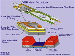 Detailed structure diagram of a GMR head assembly. Notice how small these devices are: the scale is magnified twice to get to the detail level of the GMR sensor itself, and the arm/slider/head structure at top is itself only about a quarter of an inch long.
GMR heads are comprised of four layers of thin material sandwiched together into a single structure:
1. Free Layer: This is the sensing layer, made of a nickel-iron alloy, and is passed over the surface of the data bits to be read. As its name implies, it is free to rotate in response to the magnetic patterns on the disk.
2. Spacer: This layer is nonmagnetic, typically made from copper, and is placed between the free and pinned layers to separate them magnetically.
3. Pinned Layer: This layer of cobalt material is held in a fixed magnetic orientation by virtue of its adjacency to the exchange layer.
4. Exchange Layer: This layer is made of an “antiferromagnetic” material, typically constructed from iron and manganese, and fixes the pinned layer’s magnetic orientation.
Here’s how the GMR head works in a nutshell (without getting into quantum physics that would make your brain melt–and mine. ) When the head passes over a magnetic field of one polarity (say, a “0” on the disk), the free layer has its electrons turn to be aligned with those of the pinned layer; this creates a lower resistance in the entire head structure. When the head passes over a magnetic field of the opposite polarity (“1”), the electrons in the free layer rotate so that they are not aligned with those of the pinned layer. This causes an increase in the resistance of the overall structure. The resistance changes are caused by changes to the spin characteristics of electrons in the free layer, and for this reason, IBM has named these structures spin valves. If you imagine a plumbing pipe with a rotatable shut-off valve, that’s the general concept behind the name.
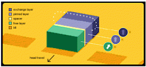 Conceptual operation of a GMR head, showing the four layers. As the head moves across a bit, electrons in the free layer rotate, increasing the resistance of the overall structure.
GMR heads are superior to conventional MR heads because they are more sensitive. While older MR heads typically exhibit a resistance change when passing from one magnetic polarity to another of about 2%, for GMR heads this is anywhere from 5% to 8%. This means GMR heads can detect much weaker and smaller signals, which is the key to increasing areal density, and thus capacity and performance. They are also much less subject to noise and interference because of their increased sensitivity, and they can be made smaller and lighter than MR heads. GMR heads are also typically fitted with “shields” that prevent them from being affected by stray magnetic fields, i.e., anything but the bit directly below the head.
GMR heads are used in the latest technology drives, which currently have capacities of up to 75 GB and areal densities of approximately 10 to 15 Gbits/in2. As of early 2000, IBM has already produced GMR heads in the lab capable of 35 Gbits/in2, suggesting that standard form factor hard disks of 200 GB and up are just around the corner.
Colossal Magnetoresistive (CMR) Heads
New giant magnetoresistive (GMR) heads are taking over the market, engineers have turned their attentions to the next breakthrough that will take hard disk read heads to the next level of performance. One of the designs being researched is an evolutionary advance based on GMR that has been dubbed by some as colossal magnetoresistive or CMR. At this stage this technology is in the early stages of investigation, and I have not been able to find much information on it. It would be logical to assume that it involves using slightly different materials than GMR in an effort to further increase sensitivity.
Data recovery Salon welcomes your comments and share with us your ideas, suggestions and experience. Data recovery salon is dedicated in sharing the most useful data recovery information with our users and only if you are good at data recovery or related knowledge, please kindly drop us an email and we will publish your article here. We need to make data recovery Salon to be the most professional and free data recovery E-book online.
World’s Top Data Recovery Hardware Tools
Easy to use at good price
Recover SATA, IDE, External HDDs, NVME SSDs, etc Order Now here
POTABLE DEVICE & NVME SSD RECOVERY TOOL
Recover USB Device and NVME SSDs at high speed! Read Details here.
DFL-PCIE DATA RECOVERY RECHARGE
Best data recovery hardware tool to start a data recovery business, read details here
RECOVER SCRATCHED HDDS

Recover lost data from scratched hard drives, read details here.
SURFACE PRO. RECOVERY
BEST HEAD REPLACEMENT TOOLS
The most cost-effective head replacement tools for Seagate, WD, Samsung, Hitachi, Toshiba, Fujitsu

